Clear Electronic Ignition Install Instructions?
Moderators: CYBORG, Oldewing, robin1731, Forum Moderators
-
Dr. Frankenstein

- Silver Member

- Posts: 721
- Joined: Sun Nov 10, 2019 7:22 am
- Location: Charlottesville, VA
Clear Electronic Ignition Install Instructions?
Okay, so I bit the bullet and got an electronic ignition setup and new coils to try out on my '78 GL1000; despite reading through the Guru's Corner, is there a clear step-by-step tutorial to setting these things up right you can point to...? My E-I came with no instructions...
-
Whiskerfish
- President

- Posts: 36936
- Joined: Thu Feb 16, 2006 9:34 pm
- My Album: http://www.ngwclub.com/gallery/v/wingmans/whiskerfish/
- Location: Norfolk Va
Re: Clear Electronic Ignition Install Instructions?
what make is it?
"Agreement is not a requirement for Respect" CDR Michael Smith USN (Ret) 2017
"The book is wrong, this whole Conclusion is Fallacious" River Tam
"Yea I do dance awkwardly, and I am having more fun than you" Taylor Swift
2008 GL1800 IIIA "TH3DOG"
1984 GL1200 Standard
1975/6/7/8/9 Arthur Fulmer Dressed Road bike
1975 Naked Noisy and Nasty in town bike
Psst. oh and by the way CHANGE YOUR BELTS!!!!
-
Dr. Frankenstein
- Silver Member
- Posts: 721
- Joined: Sun Nov 10, 2019 7:22 am
- Location: Charlottesville, VA
Re: Clear Electronic Ignition Install Instructions?
"Make"?? Don't know. Ebay, $60...It's not one of the Dyna S Let's-Talk-Financing electronic ignitions, but I don't think the engine cares about the cost as long as the signal is correct...
https://www.ngwclub.com/forum/viewtopic.php?f=1&t=77231
Shoot, maybe I answered my own question....
https://www.ngwclub.com/forum/viewtopic.php?f=1&t=77231
Shoot, maybe I answered my own question....
-
gltriker
- Honored Life Member

- Posts: 5062
- Joined: Fri Sep 24, 2010 9:11 pm
- Location: central NY State
Re: Clear Electronic Ignition Install Instructions?
Doctor John-
https://www.ngwclub.com/forum/page/ST <<<< ShopTalk link
Look at both of member Octane's Dyna S install and timing articles in ShopTalk, too.
Scroll down right side column
in addition to his generic DS1-3 link you've already located, cfairweather has an Excellent DC1-1 Ignition Coils installation document:
viewtopic.php?f=8&t=77232 note-- It includes identification of components that aren't included with the generic DC1-1 ignition coils.
We trust you already have a 12v tester . You need one to set static ignition timing of the 2 DynaS style , DS1-3 modules.
If you don't, instead of manufacturing a static timing tester light, this type of off-the-rack set-up works just as well. Dynatek company documents:
https://www.ngwclub.com/forum/page/ST <<<< ShopTalk link
Look at both of member Octane's Dyna S install and timing articles in ShopTalk, too.
Scroll down right side column
in addition to his generic DS1-3 link you've already located, cfairweather has an Excellent DC1-1 Ignition Coils installation document:
viewtopic.php?f=8&t=77232 note-- It includes identification of components that aren't included with the generic DC1-1 ignition coils.
We trust you already have a 12v tester . You need one to set static ignition timing of the 2 DynaS style , DS1-3 modules.
If you don't, instead of manufacturing a static timing tester light, this type of off-the-rack set-up works just as well.
- 20220317_191536_1647613874595_resized (1).jpg (73.07 KiB) Viewed 1234 times
Last edited by gltriker on Fri May 20, 2022 12:24 am, edited 1 time in total.
Cliff (74yrs )
Keep your eyes and ears open and you'll learn something new, everyday.
New users please visit our "Shop Talk" for common tips and help: <---jdvorchak
http://www.ngwclub.com/forum/page/ST
^^^^^^^click up here^^^^^
RE: a thorough fuel tank cleaning
"And your carbs will thank you. They no longer live down stream from a sewage plant." -gregforesi
"Can't see the paint when your looking thru the handlebars..........." -Oldewing
"I'd rather Ride than Shine" -RAT Me Too!!
Cliff
'75 GL1000 home built trike; http://www.ngwclub.com/forum/viewtopic.php?f=30&t=39996
October,2017 BOTM https://nakedgoldwingsclub.com/forum/page/Welcome
previous rides:
1953 H-D Servi-car, naked, 1969-1978 (serial#53G1559 committed to memory!)
1980 CB900 Custom (triked) 1997-2003 .... R.I.P.
Keep your eyes and ears open and you'll learn something new, everyday.
New users please visit our "Shop Talk" for common tips and help: <---jdvorchak
http://www.ngwclub.com/forum/page/ST
^^^^^^^click up here^^^^^
RE: a thorough fuel tank cleaning
"And your carbs will thank you. They no longer live down stream from a sewage plant." -gregforesi
"Can't see the paint when your looking thru the handlebars..........." -Oldewing
"I'd rather Ride than Shine" -RAT
Cliff
'75 GL1000 home built trike; http://www.ngwclub.com/forum/viewtopic.php?f=30&t=39996
October,2017 BOTM
previous rides:
1953 H-D Servi-car, naked, 1969-1978 (serial#53G1559 committed to memory!)
1980 CB900 Custom (triked) 1997-2003 .... R.I.P.
-
gltriker
- Honored Life Member
- Posts: 5062
- Joined: Fri Sep 24, 2010 9:11 pm
- Location: central NY State
Re: Clear Electronic Ignition Install Instructions?
gltriker wrote: ↑Tue Oct 19, 2021 2:08 am
A quick method to observe the primary side circuit of each ignition coil is functioning, when the engine is running, is to individually probe the two primary terminals under the rubber boot. It will not hurt the primary ignition circuits to do this. The low voltage test light bulb will flash at both primary circuits' test points in synchronization with their respective ignition coil discharge events, telling you the individual Dyna S modules are working.
If the running engine develops a "sudden loss of power", individually test both primary ignition circuits' terminals, again.
If no test light bulb flashing is observed on one circuit, that occurrence is very likely caused by a faulty Dyna S module.
edit: added here March 18th, 2022, here's the test light I use for static ignition timing. Nothing special.
A Very low watts light bulb inside the test light, for running engine primary circuits' testing purposes is an important detail, though.
Cliff (74yrs )
Keep your eyes and ears open and you'll learn something new, everyday.
New users please visit our "Shop Talk" for common tips and help: <---jdvorchak
http://www.ngwclub.com/forum/page/ST
^^^^^^^click up here^^^^^
RE: a thorough fuel tank cleaning
"And your carbs will thank you. They no longer live down stream from a sewage plant." -gregforesi
"Can't see the paint when your looking thru the handlebars..........." -Oldewing
"I'd rather Ride than Shine" -RAT Me Too!!
Cliff
'75 GL1000 home built trike; http://www.ngwclub.com/forum/viewtopic.php?f=30&t=39996
October,2017 BOTM https://nakedgoldwingsclub.com/forum/page/Welcome
previous rides:
1953 H-D Servi-car, naked, 1969-1978 (serial#53G1559 committed to memory!)
1980 CB900 Custom (triked) 1997-2003 .... R.I.P.
Keep your eyes and ears open and you'll learn something new, everyday.
New users please visit our "Shop Talk" for common tips and help: <---jdvorchak
http://www.ngwclub.com/forum/page/ST
^^^^^^^click up here^^^^^
RE: a thorough fuel tank cleaning
"And your carbs will thank you. They no longer live down stream from a sewage plant." -gregforesi
"Can't see the paint when your looking thru the handlebars..........." -Oldewing
"I'd rather Ride than Shine" -RAT
Cliff
'75 GL1000 home built trike; http://www.ngwclub.com/forum/viewtopic.php?f=30&t=39996
October,2017 BOTM
previous rides:
1953 H-D Servi-car, naked, 1969-1978 (serial#53G1559 committed to memory!)
1980 CB900 Custom (triked) 1997-2003 .... R.I.P.
-
Dr. Frankenstein
- Silver Member
- Posts: 721
- Joined: Sun Nov 10, 2019 7:22 am
- Location: Charlottesville, VA
Re: Clear Electronic Ignition Install Instructions?
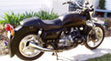
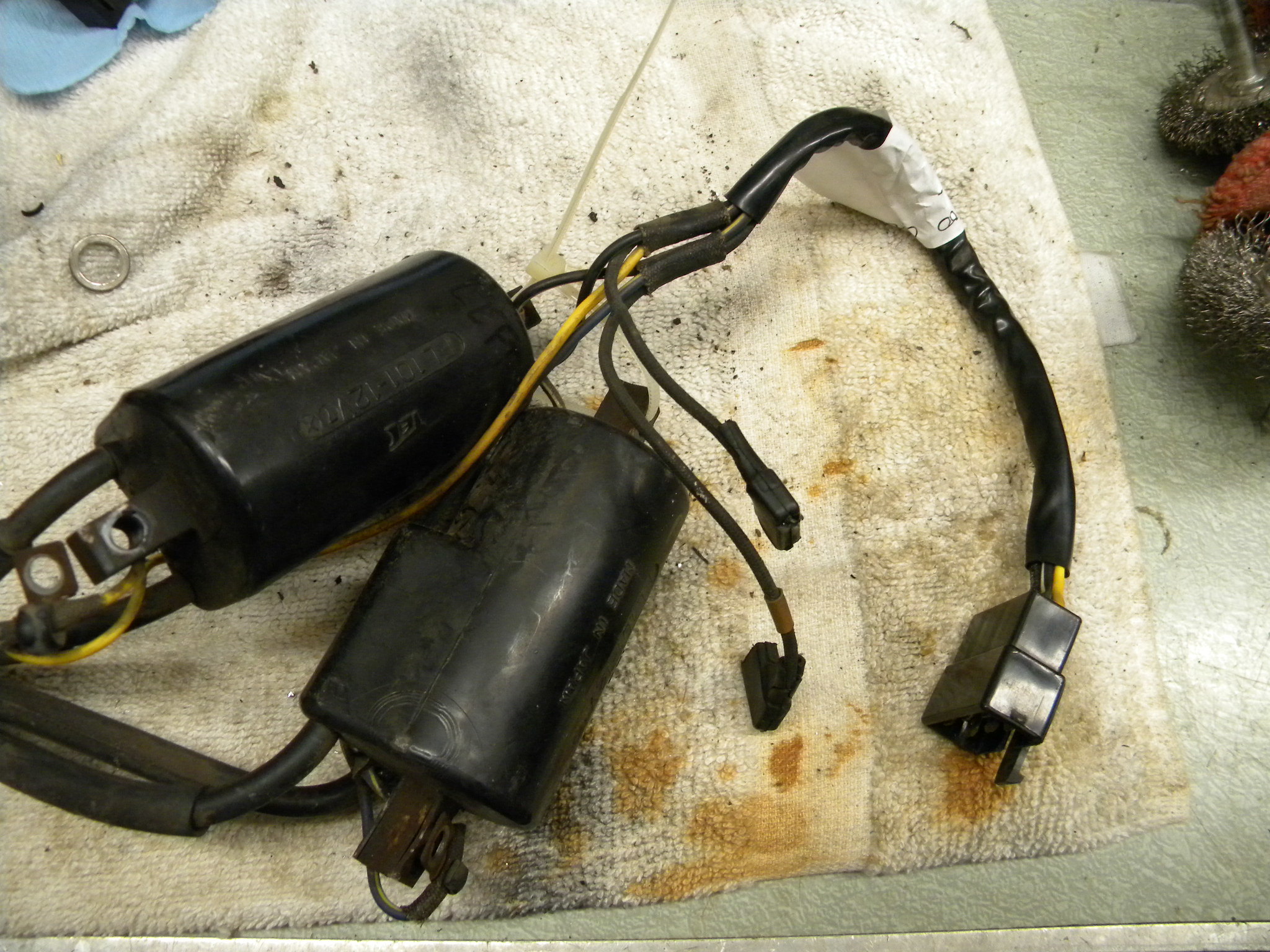
I need a little clarity here regarding the setup of new coils that go with the electronic ignition on my '78 GL1000 - cfairweather says to connect the black and brown wires together if you're planning on running new coils without the resistor, which I am planning on doing. My question is, here are the old coils and the new ones, but the black and brown wires on the old ones (as you can see) are attached to a connector - -
 DSCN2292 by Dr. Frankenstein1, on Flickr
So, do I take all the old wires out except the black and brown ones and reconnect the connector...? The yellow and green (blue?? It's hard to see/tell) ones are built into the old coils....and where are the new yellow and blue wires going again...? (Pics would be great!) I'd like to make sure I get this right - I don't want to fry any new coils...
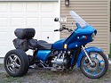
Also, here's my left shelter - I think I read somewhere I can attach the red wire for the elect. ignition to the Accessory panel - is that correct? Or does it HAVE to be attached the white/green wire...?
 DSCN2294 by Dr. Frankenstein1, on Flickr
And interestingly enough, if you look closely at the wht/grn/ wire coming out of the round thing on the bottom there, you can see a notch in it - a short, if you will. I just discovered this. This bike did not have an EI on it when I took it apart/opened it up, but I wonder if there used to be one...that's right where the EI scotchlok would go if there was one...but why would you take it back to points if you had a EI on it? Another motorcycle mystery, I guess...and where does that green wire connector behind it go to...? The lights?
DSCN2292 by Dr. Frankenstein1, on FlickrSo, do I take all the old wires out except the black and brown ones and reconnect the connector...? The yellow and green (blue?? It's hard to see/tell) ones are built into the old coils....and where are the new yellow and blue wires going again...? (Pics would be great!) I'd like to make sure I get this right - I don't want to fry any new coils...
Also, here's my left shelter - I think I read somewhere I can attach the red wire for the elect. ignition to the Accessory panel - is that correct? Or does it HAVE to be attached the white/green wire...?
DSCN2294 by Dr. Frankenstein1, on FlickrAnd interestingly enough, if you look closely at the wht/grn/ wire coming out of the round thing on the bottom there, you can see a notch in it - a short, if you will. I just discovered this. This bike did not have an EI on it when I took it apart/opened it up, but I wonder if there used to be one...that's right where the EI scotchlok would go if there was one...but why would you take it back to points if you had a EI on it? Another motorcycle mystery, I guess...and where does that green wire connector behind it go to...? The lights?
-
cfairweather
- Silver Member
- Posts: 701
- Joined: Sun Apr 13, 2014 10:37 pm
- Location: Cheyenne, Wyoming
Re: Clear Electronic Ignition Install Instructions?
The EBay generic coils and electronic ignition that look like the Dyna ones, don't come with instructions, so I wrote these two documents to help:
viewtopic.php?f=8&t=77231
viewtopic.php?f=8&t=77232
viewtopic.php?f=8&t=77231
viewtopic.php?f=8&t=77232
-
Dr. Frankenstein
- Silver Member
- Posts: 721
- Joined: Sun Nov 10, 2019 7:22 am
- Location: Charlottesville, VA
Re: Clear Electronic Ignition Install Instructions?
Yes, and on the install directions you say to join the black and blk/brn wires together if you're using those new coils, which I am.
"Note: If you decide to upgrade the coils and get rid of the ballast resistor you MUST connect the two harness wires together. These are the two wires that connect to the ballast resistor cloth covered wires. One is a male (black and brown) and the other is black. Plug these two wires into each other. See the picture below."
But as you can see in the top pic above, those two wires are connected to a connector - so I'm guessing I take all the other wires out of the connector and plug it back in and connect those two wires, yes...? That would separate the old coils from the bike and still supply power to those wires, right?
Also, I'm planning on attaching the red wire to the Accessory fuse box connector; as you mention, I think it would be easier and eliminate the need for the inline fuse, yes? (Just checking…;)
“e. Option 5: If your GL1000 is a 1978 or 1979, you can connect the red wire to the accessory fuse box connector. You won’t need the inline fuse if you do this.”
-Why not…? (I’d like to know)…
Tip: The right washer for the screw that secures the plate needs to be filed slightly so it fits better. Usually the washer diameter is slightly too large. Simply filing the edge a bit will solve the issue."
I also noticed that Yes, the right washer is a bit too big for the right screw, but even if you do file it down it should only be minimal, just to get it to fit, because the sending unit for the E-I is right on the edge of the plate, with what looks like a millimeter or less of space for the washer to sit on; and I would assume that keeping that plate from rotating due to engine vibration is a good thing…
And another question – you mentioned that if you have no condenser and connect the red wire to the Blk/Wht wire, it removes power to the coils when you use the kill switch; how does that work with the Accessory feature?
These are just some questions I’m curious about, before I hook everything up and turn it into a smoke generator…;)
-
cfairweather
- Silver Member
- Posts: 701
- Joined: Sun Apr 13, 2014 10:37 pm
- Location: Cheyenne, Wyoming
Re: Clear Electronic Ignition Install Instructions?
When I wrote the instructions, I failed to include instructions for the 78-79 models. I will try and add these later but for now here are my initial thoughts and maybe others can suggest some ideas. Since the 78-79 models use a single connector for all the wires going to the coils, I would use the original design and wiring. You would just need to make these changes:
1. Cut the wires off of the original coils (right next to the coil to keep the wires long as possible) and add connectors so you can screw them down to the new coils.
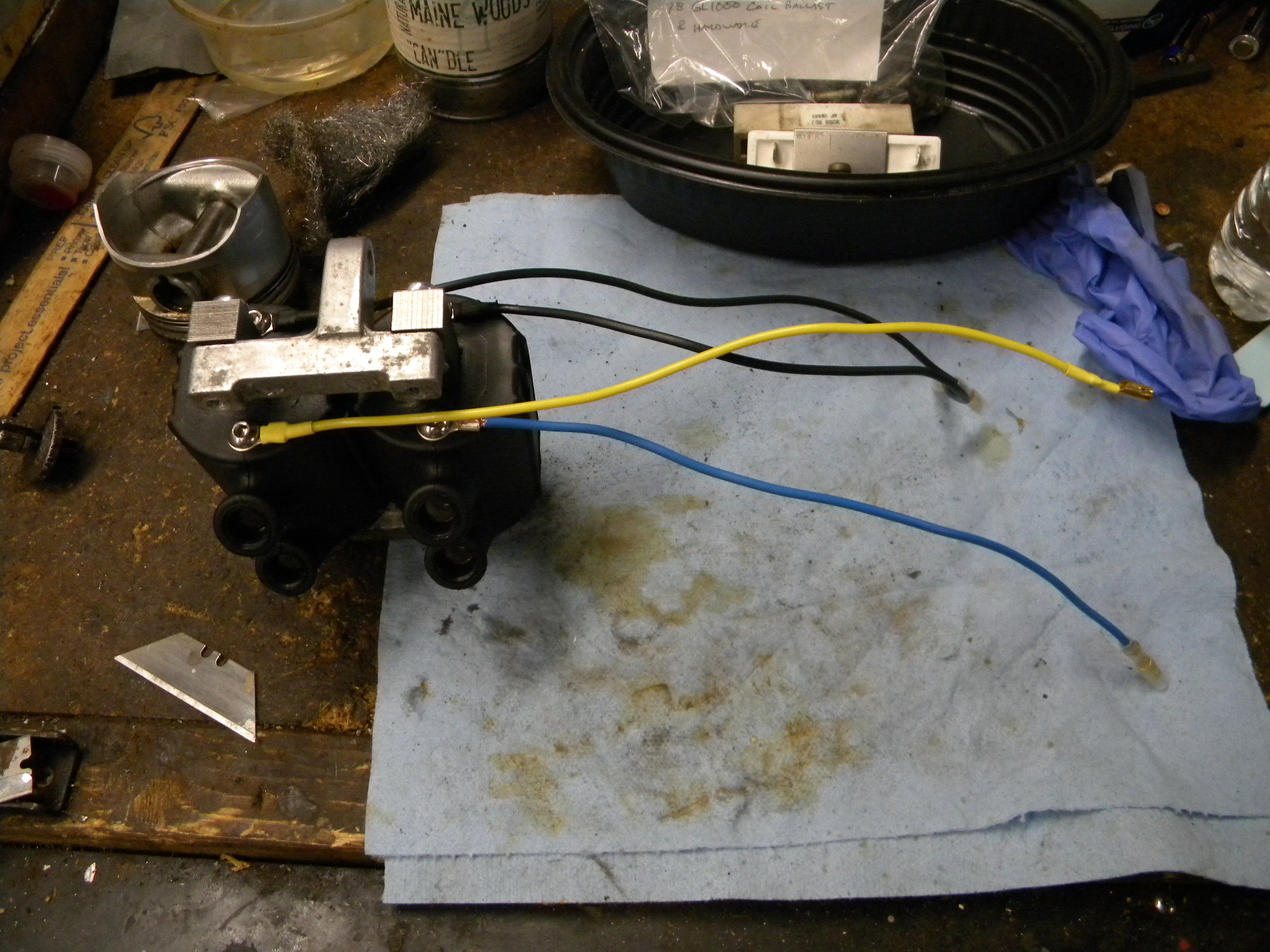
2. Remove the two wires that connect to the ballast resistor and connect them together. This presents a minor issue because they are both female so you might make a jumper wire like this:
Yes, if you use the accessory fuse, you don't need an inline fuse. Hopefully this will help until I have time to improve the instructions and provide some different options for the 78-79 models.
1. Cut the wires off of the original coils (right next to the coil to keep the wires long as possible) and add connectors so you can screw them down to the new coils.
2. Remove the two wires that connect to the ballast resistor and connect them together. This presents a minor issue because they are both female so you might make a jumper wire like this:
- DSCN4177.JPG (145.03 KiB) Viewed 1030 times
- DSCN4178.JPG (167.51 KiB) Viewed 1030 times
-
Dr. Frankenstein
- Silver Member
- Posts: 721
- Joined: Sun Nov 10, 2019 7:22 am
- Location: Charlottesville, VA
Re: Clear Electronic Ignition Install Instructions?
Right, and this is where I run into some confusion - this new coil upgrade is going on a 1978 GL1000 with a new electronic igniton; as you mentioned. "1. Cut the wires off of the original coils (right next to the coil to keep the wires long as possible) and add connectors so you can screw them down to the new coils."
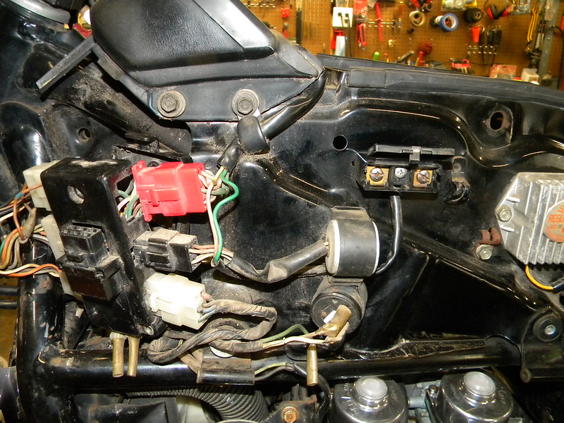
As you can see in the pic I posted of my new coils, I have copied exactly the setup you illustrated in your tutorial. At this stage, with the NEW coils, I'm wondering where those two black wires and the yellow and blue wires plug into. If you eliminate the old coils and put in the new ones, as per your setup, there is no other place for them to go except back into the connector. Here's my setup:
 DSCN2305 by Dr. Frankenstein1, on Flickr
"2. Remove the two wires that connect to the ballast resistor and connect them together." Again, these two wires go directly into the bike's wiring loom via the plastic connector where I assume they draw power from the battery, just as the original coils do..?
 DSCN2307 by Dr. Frankenstein1, on Flickr
 DSCN2306 by Dr. Frankenstein1, on Flickr
So, with the NEW coils in place, and having that connector there which plugs into the bikes wiring - couldn't you simply cut and connect the two ballast wires - - and then cut and install bullet connectors on the Black, Blu/Ylo, Yellow, and Blk/Wht wires? That way you could hook up the new upgraded coils to the bikes wiring and still use the original connector, bypassing the ballast resistor and still providing power to the coils?
I am not the sharpest tool in the shed when it comes to electricity, but it seems to me that would work for the '78 GL1000- but my knowledge of resistance, impedance, etc. is minimal. I just would like to know if I'll fry the coils if I do that.
I wouldn't think so - or am I wrong?
As you can see in the pic I posted of my new coils, I have copied exactly the setup you illustrated in your tutorial. At this stage, with the NEW coils, I'm wondering where those two black wires and the yellow and blue wires plug into. If you eliminate the old coils and put in the new ones, as per your setup, there is no other place for them to go except back into the connector. Here's my setup:
DSCN2305 by Dr. Frankenstein1, on Flickr "2. Remove the two wires that connect to the ballast resistor and connect them together." Again, these two wires go directly into the bike's wiring loom via the plastic connector where I assume they draw power from the battery, just as the original coils do..?
DSCN2307 by Dr. Frankenstein1, on FlickrDSCN2306 by Dr. Frankenstein1, on FlickrSo, with the NEW coils in place, and having that connector there which plugs into the bikes wiring - couldn't you simply cut and connect the two ballast wires - - and then cut and install bullet connectors on the Black, Blu/Ylo, Yellow, and Blk/Wht wires? That way you could hook up the new upgraded coils to the bikes wiring and still use the original connector, bypassing the ballast resistor and still providing power to the coils?
I am not the sharpest tool in the shed when it comes to electricity, but it seems to me that would work for the '78 GL1000- but my knowledge of resistance, impedance, etc. is minimal. I just would like to know if I'll fry the coils if I do that.
I wouldn't think so - or am I wrong?
-
cfairweather
- Silver Member
- Posts: 701
- Joined: Sun Apr 13, 2014 10:37 pm
- Location: Cheyenne, Wyoming
Re: Clear Electronic Ignition Install Instructions?
First, the reason you have to connect the two wires together, the ones that previously connected to the ballast resistor, is to complete the power circuit to your coils. The blue, yellow and black wires that come out of your connector that previously went to your old coils will work exactly the same going to your new coils. You added bullet connectors to your wires so you need to reconnect these to the connector. It is best to run the wires directly from the connector to the coils but if you want to use bullet connectors between the connectors and the coils it will work; however, it adds another place for a bad connections. Your DS1-3 is connected to the coil wires via your existing wiring harness connectors near the battery (where your condensers were previously plugged in to.
-
gltriker
- Honored Life Member
- Posts: 5062
- Joined: Fri Sep 24, 2010 9:11 pm
- Location: central NY State
Re: Clear Electronic Ignition Install Instructions?
John,
Yes, remove those 4 newly manufactured primary leads you installed on the new DC-1 ignition çòils being prepared for your 1978 GL1000.
Ì have a 1975 GL1000 and the primary wìre leads you manufactured from cfairweather's instructions would fit mý ignition coils' installation perfectly.
(Save those 4 new primary wire assemblys for your 1975 GL1000)
The 75-77 bikes don't have the black multiple wires plug together terminals .
So get 4 more ring terminals to utilize the primary leads you cut off where they emerge òut òf the old ignition coils.
The primary wire screw connections on the new DC1-1 ignition coils are Not polarity specific.
You do thòugh have to connect the separate yellow and blue primary wire ring terminals to their respective ignition coil to match with the assigned DS1-3 pickup on their common mounting plate.
Jumper òr by some other method permanently connect together the 2 black positivè primary leads which were originally connected to either side of the ballast resistor.
You are now all set to plug the 2 mating black hard plastic terminal blocks back together and good tò go.
I will find a photo of mý 1975 primary wires connectors.
75-77 utilize color matched wìres màle and female bullet connectors.
SPECIAL NOTE!
The red wire Ì have routed to the positive post on both coils on my trike comes from a 12v relay. Normally a separate black/white wire is directed to both ignition coils
Yes, remove those 4 newly manufactured primary leads you installed on the new DC-1 ignition çòils being prepared for your 1978 GL1000.
Ì have a 1975 GL1000 and the primary wìre leads you manufactured from cfairweather's instructions would fit mý ignition coils' installation perfectly.
(Save those 4 new primary wire assemblys for your 1975 GL1000)
The 75-77 bikes don't have the black multiple wires plug together terminals .
So get 4 more ring terminals to utilize the primary leads you cut off where they emerge òut òf the old ignition coils.
The primary wire screw connections on the new DC1-1 ignition coils are Not polarity specific.
You do thòugh have to connect the separate yellow and blue primary wire ring terminals to their respective ignition coil to match with the assigned DS1-3 pickup on their common mounting plate.
Jumper òr by some other method permanently connect together the 2 black positivè primary leads which were originally connected to either side of the ballast resistor.
You are now all set to plug the 2 mating black hard plastic terminal blocks back together and good tò go.
I will find a photo of mý 1975 primary wires connectors.
75-77 utilize color matched wìres màle and female bullet connectors.
- 20190604_172301_resized_1.jpg (129.47 KiB) Viewed 983 times
- 20190604_170059_resized.jpg (106.36 KiB) Viewed 983 times
- 20190604_172843_resized.jpg (123.5 KiB) Viewed 983 times
- 20190604_173648_1653838198474_resized.jpg (130.4 KiB) Viewed 983 times
The red wire Ì have routed to the positive post on both coils on my trike comes from a 12v relay. Normally a separate black/white wire is directed to both ignition coils
- 20190604_170819_resized.jpg (128.73 KiB) Viewed 973 times
Last edited by gltriker on Sun May 29, 2022 1:47 pm, edited 7 times in total.
Cliff (74yrs )
Keep your eyes and ears open and you'll learn something new, everyday.
New users please visit our "Shop Talk" for common tips and help: <---jdvorchak
http://www.ngwclub.com/forum/page/ST
^^^^^^^click up here^^^^^
RE: a thorough fuel tank cleaning
"And your carbs will thank you. They no longer live down stream from a sewage plant." -gregforesi
"Can't see the paint when your looking thru the handlebars..........." -Oldewing
"I'd rather Ride than Shine" -RAT Me Too!!
Cliff
'75 GL1000 home built trike; http://www.ngwclub.com/forum/viewtopic.php?f=30&t=39996
October,2017 BOTM https://nakedgoldwingsclub.com/forum/page/Welcome
previous rides:
1953 H-D Servi-car, naked, 1969-1978 (serial#53G1559 committed to memory!)
1980 CB900 Custom (triked) 1997-2003 .... R.I.P.
Keep your eyes and ears open and you'll learn something new, everyday.
New users please visit our "Shop Talk" for common tips and help: <---jdvorchak
http://www.ngwclub.com/forum/page/ST
^^^^^^^click up here^^^^^
RE: a thorough fuel tank cleaning
"And your carbs will thank you. They no longer live down stream from a sewage plant." -gregforesi
"Can't see the paint when your looking thru the handlebars..........." -Oldewing
"I'd rather Ride than Shine" -RAT
Cliff
'75 GL1000 home built trike; http://www.ngwclub.com/forum/viewtopic.php?f=30&t=39996
October,2017 BOTM
previous rides:
1953 H-D Servi-car, naked, 1969-1978 (serial#53G1559 committed to memory!)
1980 CB900 Custom (triked) 1997-2003 .... R.I.P.
-
Dr. Frankenstein
- Silver Member
- Posts: 721
- Joined: Sun Nov 10, 2019 7:22 am
- Location: Charlottesville, VA
Re: Clear Electronic Ignition Install Instructions?
cfairweather:
"It is best to run the wires directly from the connector to the coils..."
Yes, I think so too - I just ordered some 6.3mm quick-splice terminals to do just that - I needed some anyway.
But 'bottom-line' that setup should work, yes? Connect a jumper to the two female connectors off the ballast resistor, and then run the two black wires and the yellow and blue wire back into their respective spots in the connector...?
Because there's no polarity in the coils, it shouldn't matter which black wire goes where in the connector, does it?
(You'll have to forgive me, I'm just very cautious when it comes to electricity - most electrical components you can't send back once you hook them up).
Cliff: the process I'm talking about here is going on a '78 GL1000, the one I'm rebuilding right now...However, I DO have a '75 GL1000 that I would like to do this to as well, so if the setup you have is different, pics are a great help!
Case-in-Point: "Primary Leads??" You mean the black ones or the yellow and blue ones??
Look, it took me 2 1/2 years and a summer school session to pass basic Algebra; I learned geometry on a pool table; I don't even want to talk about a Basic Electronics course I took that I crashed and burned in - and people wonder why I drink!
("Technically, alcohol IS a solution.")
("You don't need alcohol to have fun." True - and you don't need shoes to run in either, but it makes it a helluva lot easier!)
-
gltriker
- Honored Life Member
- Posts: 5062
- Joined: Fri Sep 24, 2010 9:11 pm
- Location: central NY State
Re: Clear Electronic Ignition Install Instructions?
Primary ignition circuit wires are the small gauge wires leading into the ignition coil.
Black/white wires are positive current conductors into the coil.
The yellow and blue wires are independently the negative current side conductors going into their respective ignition coil.
12:36 pm
ĢO BACK TO MY updated POST #12 for pretty pictures
Black/white wires are positive current conductors into the coil.
The yellow and blue wires are independently the negative current side conductors going into their respective ignition coil.
12:36 pm
ĢO BACK TO MY updated POST #12 for pretty pictures
Cliff (74yrs )
Keep your eyes and ears open and you'll learn something new, everyday.
New users please visit our "Shop Talk" for common tips and help: <---jdvorchak
http://www.ngwclub.com/forum/page/ST
^^^^^^^click up here^^^^^
RE: a thorough fuel tank cleaning
"And your carbs will thank you. They no longer live down stream from a sewage plant." -gregforesi
"Can't see the paint when your looking thru the handlebars..........." -Oldewing
"I'd rather Ride than Shine" -RAT Me Too!!
Cliff
'75 GL1000 home built trike; http://www.ngwclub.com/forum/viewtopic.php?f=30&t=39996
October,2017 BOTM https://nakedgoldwingsclub.com/forum/page/Welcome
previous rides:
1953 H-D Servi-car, naked, 1969-1978 (serial#53G1559 committed to memory!)
1980 CB900 Custom (triked) 1997-2003 .... R.I.P.
Keep your eyes and ears open and you'll learn something new, everyday.
New users please visit our "Shop Talk" for common tips and help: <---jdvorchak
http://www.ngwclub.com/forum/page/ST
^^^^^^^click up here^^^^^
RE: a thorough fuel tank cleaning
"And your carbs will thank you. They no longer live down stream from a sewage plant." -gregforesi
"Can't see the paint when your looking thru the handlebars..........." -Oldewing
"I'd rather Ride than Shine" -RAT
Cliff
'75 GL1000 home built trike; http://www.ngwclub.com/forum/viewtopic.php?f=30&t=39996
October,2017 BOTM
previous rides:
1953 H-D Servi-car, naked, 1969-1978 (serial#53G1559 committed to memory!)
1980 CB900 Custom (triked) 1997-2003 .... R.I.P.
-
Dr. Frankenstein
- Silver Member
- Posts: 721
- Joined: Sun Nov 10, 2019 7:22 am
- Location: Charlottesville, VA
Re: Clear Electronic Ignition Install Instructions?
Silly Question Number One: with the electronic ignition installed, do the coils and plugs need to be in as well in order to time it? I would assume Yes, because you're reading the signal through the coils, yes...?
-
- Similar Topics
- Replies
- Views
- Last post
-
- 43 Replies
- 3502 Views
-
Last post by Sidecar Bob
-
- 4 Replies
- 303 Views
-
Last post by SnoBrdr
-
- 4 Replies
- 401 Views
-
Last post by silverbullit
-
- 0 Replies
- 4042 Views
-
Last post by Whiskerfish
-
- 9 Replies
- 796 Views
-
Last post by elslimdiablo