Bike of the Year Voting in the Clubhouse.
Voting closes 17 December 9:22 PM
LAST DAY Make your voice heard!
click here: viewtopic.php?t=79374#p833813
Voting closes 17 December 9:22 PM
LAST DAY Make your voice heard!
click here: viewtopic.php?t=79374#p833813
My EFI setup
Moderators: sunnbobb, Neil, Forum Moderators
-
CharlieP

- Platinum Member

- Posts: 1710
- Joined: Sat Apr 05, 2008 6:10 pm
- Location: Bend,Oregon
Re: My EFI setup
neato torpedo
Growing Old is Mandatory ** Growing Up is Optional
http://www.ngwclub.com/gallery/v/wingmans/Chasdog/
http://www.ngwclub.com/gallery/v/wingmans/Chasdog/
-
socrace
- Titanium Member

- Posts: 334
- Joined: Sun Aug 16, 2009 11:46 pm
- Location: Springfield, Ill.
Re: My EFI setup
Yeah, got lucky on ebay with the '85 efi assembly, was $138 + shipping.
http://cgi.ebay.com/ebaymotors/ws/eBayI ... 500wt_1182
Here is a picture if the link is gone: And here it is stripped down and sitting in the gl1100: The manifolds actually bolt up to the heads perfectly, except the airbox between them is about .6" too wide. Will take a 0.6" section out of the right side of the airbox which will leave the air filter hole centered and the stock gl1200 filter fits well. It seems likely that the designers of this unit used a gl1100 for their original mockup, it really fits in there good.
I agree that GM sensors should work well, am planning to mount the coolant sensor where the fan switch was, and control the fan with the ecu. Some Steinhart Hart constants that are very accurate for these sensors are a=1.4531E-03 b=2.3385E-04 c=8.5100E-08. Also plan to use a single 1bar GM MAP sensor T'd into all the manifolds for main fuel lookup. Will probably keep the Honda TPS sensor, assuming it works ok haven't tested it yet.
Have a small electric pump (carter p74042, $9 NOS on ebay) that will mount inside the tank hanging from the fuel level sensor. The best external pump with hose barbs I could find (airtex E8312, http://www.rockauto.com/catalog/moreinfo.php?pk=60014) would take up more space, cost more.
And finally, have installed a regulator/rectifier from a 2006 Honda CBR600RR. It is Shindengen MOSFET unit model FH008EB, $35 on ebay. My research on the net shows this unit should provide enough clean power at idle to run the efi, as it does on the CBR which has a similar sized 3 phase permanent magnet alternator to ours.
Now, if I can just stay focused.. As somebody once said: "The last 2% of the project will take 200% of the time".
You do not have the required permissions to view the files attached to this post.
1981 Goldwing Standard - efi'd, other stuff
-
Cookie

- Honored Life Member

- Posts: 15821
- Joined: Thu Oct 25, 2007 11:37 pm
- RIP: 1950-2011
- Location: San Mateo, CA
Re: My EFI setup
I've had a hard enough time getting my carbs to work..more power to ya Ray.
Enjoy life,
Cookie
A guy with two sidecars can't be all bad.
Owner of 4.4 76s and one lone 75 Wings (does a spare engine make .2?)
Cookie
A guy with two sidecars can't be all bad.
Owner of 4.4 76s and one lone 75 Wings (does a spare engine make .2?)
-
Whiskerfish
- President

- Posts: 38138
- Joined: Thu Feb 16, 2006 9:34 pm
- My Album: http://www.ngwclub.com/gallery/v/wingmans/whiskerfish/
- Location: Norfolk Va
Re: My EFI setup
Great answer Ray I actually understood it!!! Thanks
"Agreement is not a requirement for Respect" CDR Michael Smith USN (Ret) 2017
"The book is wrong, this whole Conclusion is Fallacious" River Tam
"Yea I do dance awkwardly, and I am having more fun than you" Taylor Swift
2008 GL1800 IIIA "TH3DOG"
1984 GL1200 Standard
1975/6/7/8/9 Arthur Fulmer Dressed Road bike
1975 Naked Noisy and Nasty in town bike
Psst. oh and by the way CHANGE YOUR BELTS!!!!
-
morganfrmn

- True Blue Steel Biker

- Posts: 2101
- Joined: Sun Feb 01, 2009 11:33 am
- My Album: http://www.ngwclub.com/gallery/main.php?g2_itemId=2743
- Location: louisville kentucky
- Contact:
Re: My EFI setup
so are you doing the high preasure fuel pump with a return to the tank...
Click here and you can see my motorcycle
(http://www.ngwclub.com/gallery/main.php?g2_itemId=2743)
(http://www.facebook.com/morganfrmn)
(http://www.ngwclub.com/gallery/main.php?g2_itemId=2743)
(http://www.facebook.com/morganfrmn)
-
KYpondman
- True Blue Steel Biker
- Posts: 2281
- Joined: Wed Jun 10, 2009 7:04 pm
- Location: 3542 Overridge Circle, Adams, TN
Re: My EFI setup
I don't plan on doing this in the foreseeable future, but it's fun going along for the ride.
Thanks for your efforts,
Claude
Thanks for your efforts,
Claude
In the 60's, people took acid to make the world weird.
Now the world is Weird and people take Prozac to make it normal.
RETIRED and LOVING It!!! anim-cheers1
82 GL1100 Standard (gone to Gson in Oregon) action1
84 GL1200 standard with Hondaline bags.
84 GL1200 dressed naked with everything to return to naked.(gone to Gson in Oregon) action1
Now the world is Weird and people take Prozac to make it normal.
RETIRED and LOVING It!!! anim-cheers1
82 GL1100 Standard (gone to Gson in Oregon) action1
84 GL1200 standard with Hondaline bags.
84 GL1200 dressed naked with everything to return to naked.(gone to Gson in Oregon) action1
-
taunusrainer
- Silver Member

- Posts: 944
- Joined: Wed Oct 04, 2006 2:57 pm
Re: My EFI setup
That is exactly what I did!I agree that GM sensors should work well, am planning to mount the coolant sensor where the fan switch was, and control the fan with the ecu.
What is this?????Some Steinhart Hart constants that are very accurate for these sensors are a=1.4531E-03 b=2.3385E-04 c=8.5100E-08.
I will sync the elbows and then use one sync port for the MAP. There is a MAP sensor built in the megasquirt. Will use this one.Also plan to use a single 1bar GM MAP sensor T'd into all the manifolds for main fuel lookup.
Any linear TPS will be good.Will probably keep the Honda TPS sensor, assuming it works ok haven't tested it yet.
Do You intend to cut and weld it?Will take a 0.6" section out of the right side of the airbox which will leave the air filter hole centered and the stock gl1200 filter fits well
I am wonderin if there were different SEi injections...I was able to grab a set of SEi intake elbows and they did not fit onto my cylinder heads...
Another question:
What is the tubing underneath the SEI system for:

Ray
1976 GL1000 test mule
1977 GL1000 in parts, rebuild in progress
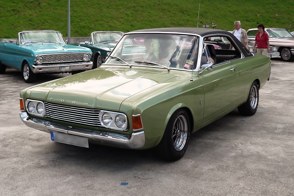
1969 Ford 17m 2.3V6
1976 Ford Cortina 2.3V6 (Propane)
1990 Mustang 5.0 7up conv.
1998 Peugeot 406 Coupe (Propane)
1977 GL1000 in parts, rebuild in progress
1969 Ford 17m 2.3V6
1976 Ford Cortina 2.3V6 (Propane)
1990 Mustang 5.0 7up conv.
1998 Peugeot 406 Coupe (Propane)
-
Whiskerfish
- President
- Posts: 38138
- Joined: Thu Feb 16, 2006 9:34 pm
- My Album: http://www.ngwclub.com/gallery/v/wingmans/whiskerfish/
- Location: Norfolk Va
Re: My EFI setup
I remember talking about those extra tubes with Cyborg just a couple of weeks ago. I will drop him a note to check in here if he can.
"Agreement is not a requirement for Respect" CDR Michael Smith USN (Ret) 2017
"The book is wrong, this whole Conclusion is Fallacious" River Tam
"Yea I do dance awkwardly, and I am having more fun than you" Taylor Swift
2008 GL1800 IIIA "TH3DOG"
1984 GL1200 Standard
1975/6/7/8/9 Arthur Fulmer Dressed Road bike
1975 Naked Noisy and Nasty in town bike
Psst. oh and by the way CHANGE YOUR BELTS!!!!
"The book is wrong, this whole Conclusion is Fallacious" River Tam
"Yea I do dance awkwardly, and I am having more fun than you" Taylor Swift
2008 GL1800 IIIA "TH3DOG"
1984 GL1200 Standard
1975/6/7/8/9 Arthur Fulmer Dressed Road bike
1975 Naked Noisy and Nasty in town bike
Psst. oh and by the way CHANGE YOUR BELTS!!!!
-
socrace
- Titanium Member
- Posts: 334
- Joined: Sun Aug 16, 2009 11:46 pm
- Location: Springfield, Ill.
Re: My EFI setup
Hi Ray, thanks for the comments.
Yeah, need to cut a .6" strip out of the airbox (front to back on right side) and then weld it back together. May mock it up using jb weld to make sure it's aligned correctly, then take it off and get it tig welded. Or maybe just go with jb weld, or try to braze it myself, can decide yet..
Have done a fair amount of research on the LTD, but not so much on the SEI, am surprised as well that the manifolds are different! Do you have pictures?
OK, here is what I (think I) know about the tubing on the LTD:
Green arrows - These are the idle air hoses, notice the elbows connect to the throttle bodies just downstream of the throttle plates. Strangely, the LTD does not have any ecu control over idle speed, idle air in increased when cold through mechanical means. The small metal boxes that the red hoses connect to have one-way reed valves in them, another bit of strangeness. From there, the hoses converge into one hose that connects to to an electrically powered thermostatic air valve, which heats up and closes, similar to an electric choke on a 60's VW.
Red arrows - These are the so-called secondary air injection hoses (emissions gadget). The oval shaped bumps on the intake manifolds hold the o-ringed ends down on machined holes in the 1200 cylinder heads. Once removed, this whole assembly leaves a 1/2" or so hole in the bottom of the airbox.
Yellow arrows - These are the 4 MAP sensor connections.
Have to say I'm a little worried about those reed valves in the idle air system, have you ever run into this before? Current plan is to run 4 equal length hoses out to a Ford/Bosch PWM solenoid air valve to control idle, no reed valves.
Another pict: Bob D
You do not have the required permissions to view the files attached to this post.
1981 Goldwing Standard - efi'd, other stuff
-
Old Fogey

- Honored Life Member
- Posts: 7814
- Joined: Mon Aug 27, 2007 11:31 pm
- Location: Glasgow, Scotland
- Contact:
Re: My EFI setup
Ray,
I've been trying to find time to scan the 86 SE-i manual I acquired for Cyborg.
In the meantime here's a scan of the tube arrangement.
If there is anything else you need let me know and I'll scan it for you.

I've been trying to find time to scan the 86 SE-i manual I acquired for Cyborg.
In the meantime here's a scan of the tube arrangement.
If there is anything else you need let me know and I'll scan it for you.
"Impossible Is Just a Level of Difficulty!..."
If I'd wanted you to understand, I would have explained it better! (Johann Cruyff)
I’d give my right arm to be ambidextrous!
If I'd wanted you to understand, I would have explained it better! (Johann Cruyff)
I’d give my right arm to be ambidextrous!
-
sunnbobb

- Facebook Admin

- Posts: 21331
- Joined: Thu Jan 10, 2008 4:09 pm
- My Album: http://www.ngwclub.com/gallery/v/wingmans/sunnbobb/
- Location: LaConner, WA
Re: My EFI setup
Ah. The dreaded "California Model"
I found the end of the internet
---- Bradshaw Bikes custom polishing for your wing. Visit us on facebook!
1978 Learning Experience
1980 County Road Hauler "Brain Damage"
1978 Cafe Custom Gl1000 "Vyper"
1977 Bulldog Inspired "Vaincre"
1981 Street Fighter GL1100 "No Quarter"
1983 Supercharged Street Drag "Anubis" (in worx)
1983 gl1100 mint restoration "Kristen"
1985 Aspencade..pondering.
-
Old Fogey
- Honored Life Member
- Posts: 7814
- Joined: Mon Aug 27, 2007 11:31 pm
- Location: Glasgow, Scotland
- Contact:
Re: My EFI setup
This might help also

"Impossible Is Just a Level of Difficulty!..."
If I'd wanted you to understand, I would have explained it better! (Johann Cruyff)
I’d give my right arm to be ambidextrous!
If I'd wanted you to understand, I would have explained it better! (Johann Cruyff)
I’d give my right arm to be ambidextrous!
-
taunusrainer
- Silver Member
- Posts: 944
- Joined: Wed Oct 04, 2006 2:57 pm
Re: My EFI setup
I understand. Thank You, gentlemen. This info is very helpful. Seems the SEi was quite a green vehicle then in the eighties...did it have an oxygen sensor in the exhaust?
I also do not quite understand why they connected the vacuum sync ports to feed the MAP sensor. The throttles are factory synced so one single vaccuum should be enough. Even if they are out of spec, i.e. not synced, creating an average vaccuum cannot cure the performance.
Fogey You seem to have a whole library at home
Great! Thank You! I'll sooner or later come back to this offer
Socrace, unless You are not an incredibly perfect welding pro, You should not even think of welding this material. It is nearly impossible. The guy who welded my intake elbows is a trailer maker. You should see how beautiful he normally welds. He said the elbows nearly drove him crazy...
I would drill and tap the halves, bolt them together with some suitable hardware

and then epoxy it.
CU
Ray
I also do not quite understand why they connected the vacuum sync ports to feed the MAP sensor. The throttles are factory synced so one single vaccuum should be enough. Even if they are out of spec, i.e. not synced, creating an average vaccuum cannot cure the performance.
Fogey You seem to have a whole library at home
Great! Thank You! I'll sooner or later come back to this offer
Socrace, unless You are not an incredibly perfect welding pro, You should not even think of welding this material. It is nearly impossible. The guy who welded my intake elbows is a trailer maker. You should see how beautiful he normally welds. He said the elbows nearly drove him crazy...
I would drill and tap the halves, bolt them together with some suitable hardware
and then epoxy it.
Yes, this is the way to go imo.Have to say I'm a little worried about those reed valves in the idle air system, have you ever run into this before? Current plan is to run 4 equal length hoses out to a Ford/Bosch PWM solenoid air valve to control idle, no reed valves.
CU
Ray
1976 GL1000 test mule
1977 GL1000 in parts, rebuild in progress
1969 Ford 17m 2.3V6
1976 Ford Cortina 2.3V6 (Propane)
1990 Mustang 5.0 7up conv.
1998 Peugeot 406 Coupe (Propane)
1977 GL1000 in parts, rebuild in progress
1969 Ford 17m 2.3V6
1976 Ford Cortina 2.3V6 (Propane)
1990 Mustang 5.0 7up conv.
1998 Peugeot 406 Coupe (Propane)
-
FirstYearDeek

- True Blue Steel Biker
- Posts: 2543
- Joined: Sun Aug 10, 2008 4:41 pm
- Location: Terre Haute, Indiana
Re: My EFI setup
Looks like a great start, Ray!
I agree that a central throttle body with port injectors is the way to go. You've still got the whole "synchronizing" thing to go through now.
Although it should be slightly easier with injectors as a fuel source... When you're syncing, use a map that has "flat" fueling all over the idle range and turn off all the automatic enrichment settings. That way fuel stays constant while you mess with the throttle plates.
-Deek
"Eat, drink and be merry. For tomorrow we die."
1975 GL 1000 (First Year) under the knife; soon to be a cafe' inspired "Boss" of a freedom machine.
1975 GL 1000 (First Year) under the knife; soon to be a cafe' inspired "Boss" of a freedom machine.
-
FirstYearDeek
- True Blue Steel Biker
- Posts: 2543
- Joined: Sun Aug 10, 2008 4:41 pm
- Location: Terre Haute, Indiana
Re: My EFI setup
RE: reed valves...
This is a batch fire system; not sequential. Even sequential systems don't have time in the cycle to time injection only when the valve is open, so there is always fuel/air waiting in the ports. Because the secondary air injection system is downstream from the throttles, the cylinder on the intake stroke could potentially suck fuel/air right out of the other cylinders, totally hosing up the mixture.
-Deek
This is a batch fire system; not sequential. Even sequential systems don't have time in the cycle to time injection only when the valve is open, so there is always fuel/air waiting in the ports. Because the secondary air injection system is downstream from the throttles, the cylinder on the intake stroke could potentially suck fuel/air right out of the other cylinders, totally hosing up the mixture.
Yep. Ditch all that crap and let the FIDLE do it's job! (Hose length is not really that important on an idle system; don't sweat the "equal length" part... a longer hose isn't going to change the total volume or velocity enough to matter, and it will make your hose routing neater.)taunusrainer wrote:Current plan is to run 4 equal length hoses out to a Ford/Bosch PWM solenoid air valve to control idle, no reed valves.
-Deek
"Eat, drink and be merry. For tomorrow we die."
1975 GL 1000 (First Year) under the knife; soon to be a cafe' inspired "Boss" of a freedom machine.
1975 GL 1000 (First Year) under the knife; soon to be a cafe' inspired "Boss" of a freedom machine.