
installing the DYNA electronic ignition,
both from folks having trouble doing it,
and folks asking if it's difficult etc.
So time for a "How-To":
I'll be following the order (more or less) that DYNA gives in their
installation instructions.
I'm just adding pictures and a bit of blahblah.
NOTE: this is the newest edition of the DYNA
which means that it comes with a ballast resistor.
This installation is for installing the DYNA
retaining the original coils.
More on installing High Performance coils
to come later.
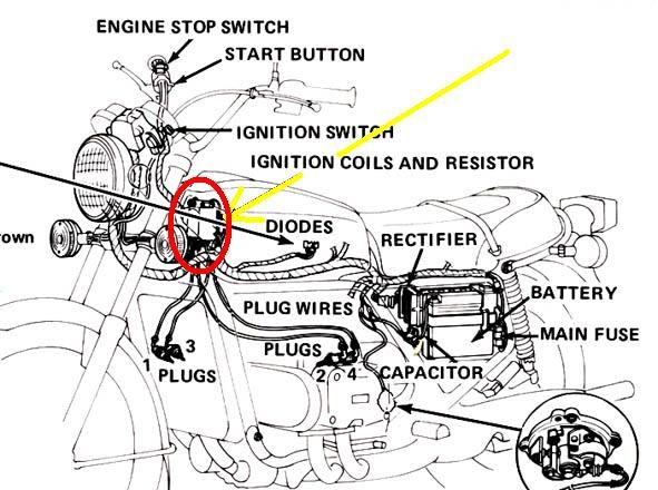
Find your coils/resistor set-up.
Should be somewhere around here:
..so open the lid to your 'glove compartment'
..remove plastic tray
..remove air filter / air-filter box
You can just about see them there,
right behind the middle frame tube.
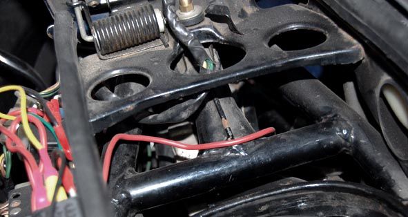
This shows where they are (if your false tank was off)
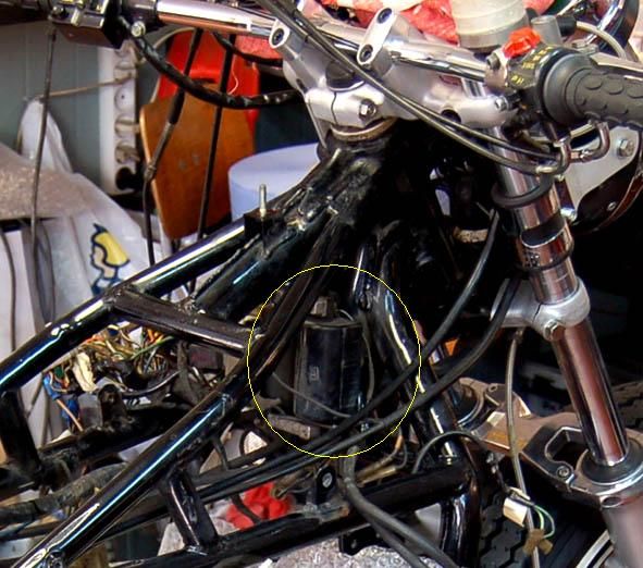
and anyway it's easier to see it this way:
(NOT that you need to, or should, remove them from the frame!!!)
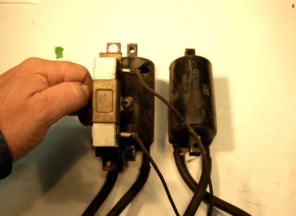
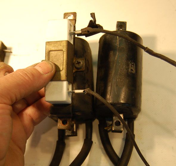
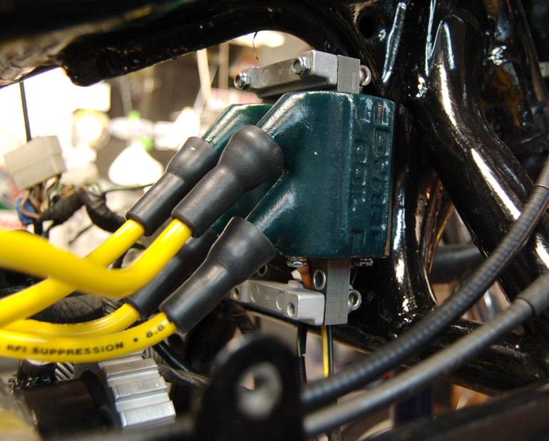
Ballast resistor (white thingy) and coils.
(Now if any of your coils is cracked like the one on the right
you better order a new one right now)
..remove the two wires from the resistor
and remove ballast resistor:
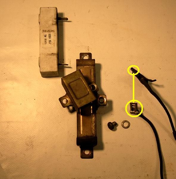
..grab the resistor that comes with the DYNA-set
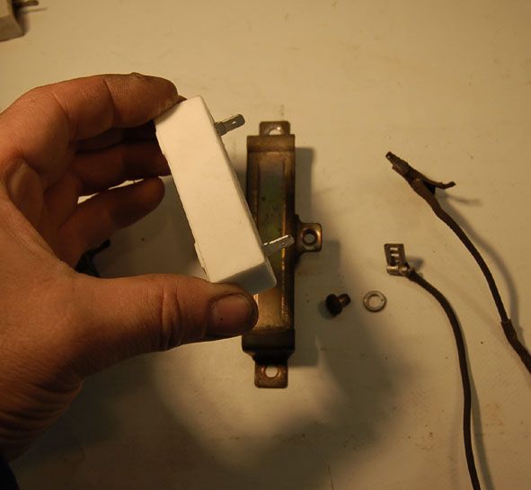
..mount it just like the original one
..connect wires
(*) Please see note at the end of the post
IF you are installing the Dyna Hi-Performance Coils
..remount air filter/box etc.
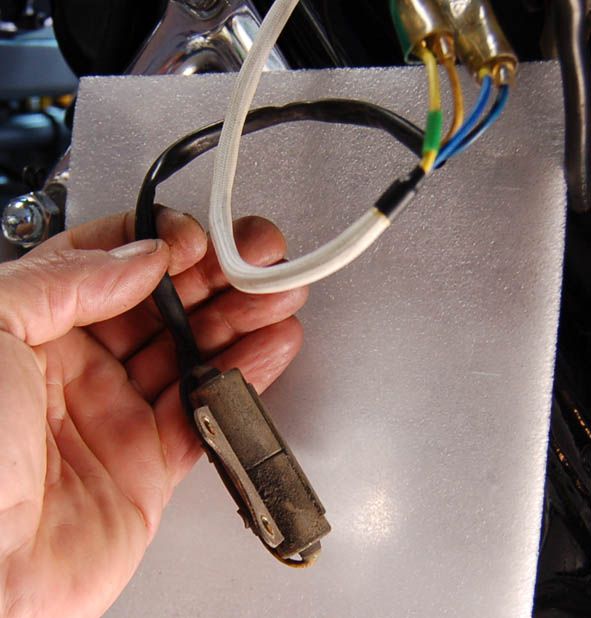
Open side cover and locate the turn signal flasher,
and grab the WHITE/GREEN wire that runs to it
On the Euro-spec bikes the signal flasher looks like this
(cylinder-shaped thin on the left)
Don't be confused about this set-up. A few things are different
on US-bikes; you have the Reserve Lightning System etc.
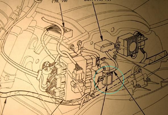
On early bikes it will look like this:
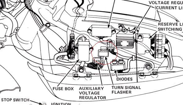
and on 79-80 bikes like this:
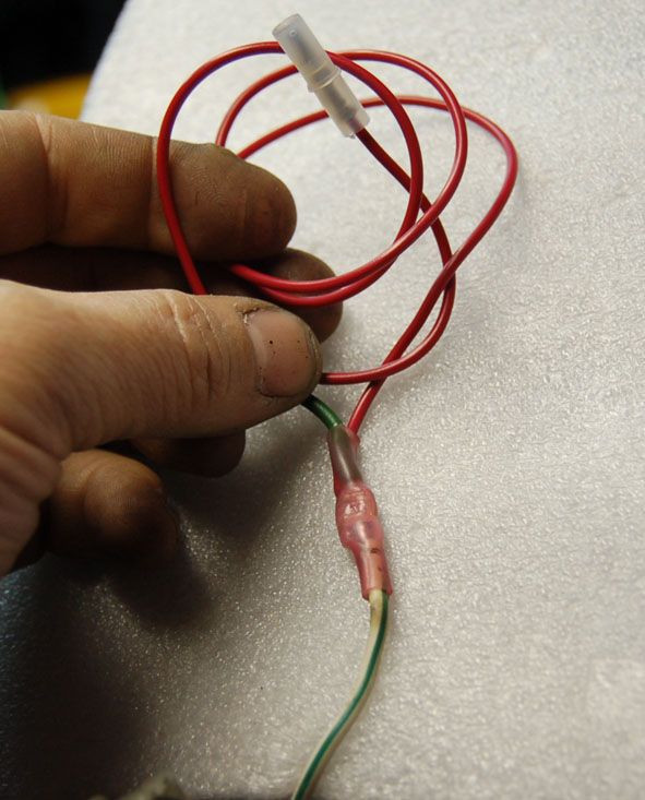
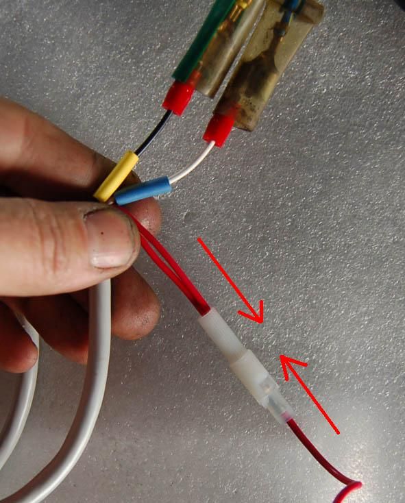
Now connect the WHITE/GREEN wire you just found
to the (separate) RED wire supplied with the kit.
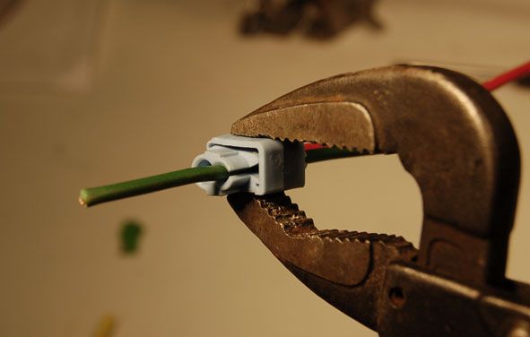
You can do as described in the instructions;
use the push clip, in which case please be careful
using that silly plastic-thing.
To press it together;
use a tool with two 'surfaces'
to press the two sides of the clip together, (no sharp tool)
as 'parallel as possible:
or you connect it by some other mean, like soldering
and protecting the soldering like this:
Now bend down
..remove the points cover
..remove 10 mm bolt
..remove left side screw (this one has an non-original allen bolt)
..remove right side screw
..remove points plate assembly
Remove battery-side-cover.
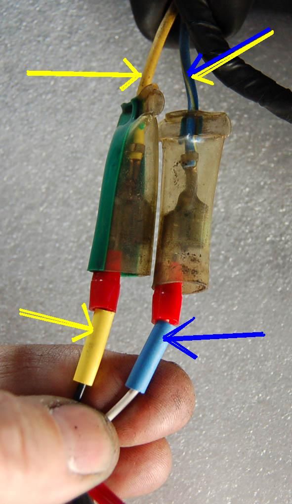
Find where the original points-wires plugs in.
Roll back that rubber-'sock'
and find two wires:
BLUE/YELLOW
and
YELLOW
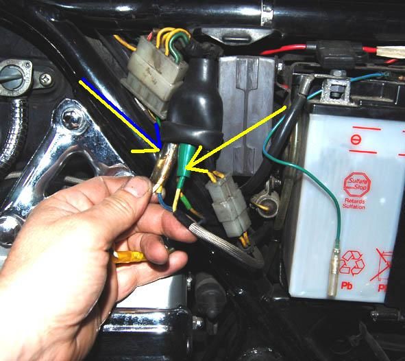
Up close it looks like this
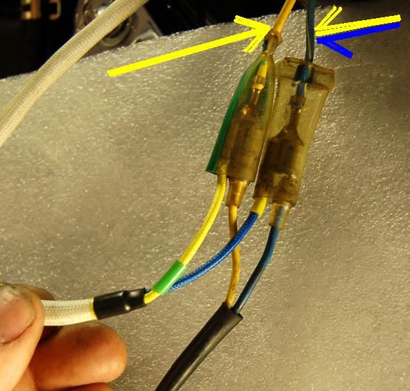
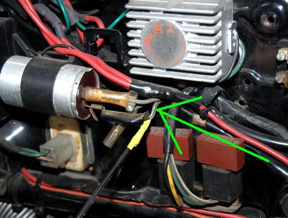
Now route the DYNA wires:
BLACK 3 and 4 cylinder wire with or without YELLOW 'collar'
and
WHITE 1 and 2 cylinder wire with or without BLUE 'collar'
from down where the points were, and follow
the original wire-routing up to next to the battery.
Attach them like this
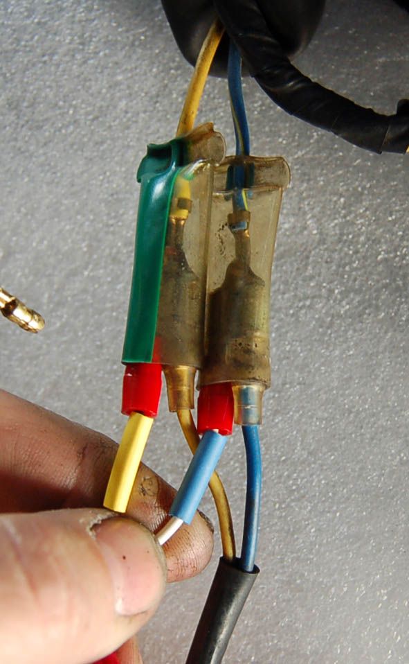
Those two other wires going into the connectors (and 'down' (on the pic))
you don't need anymore,
They lead down to the condensers:
(which are attached to the side of the battery-box).
Anyway; you don't need them anymore
so unplug them.
Things should look like this now;
(I'm straying away from the DYNA instructions here)
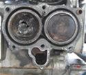
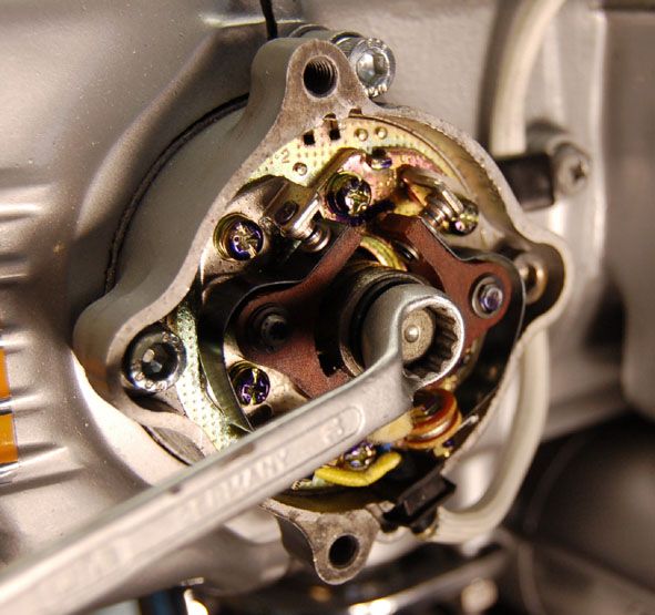
Back down
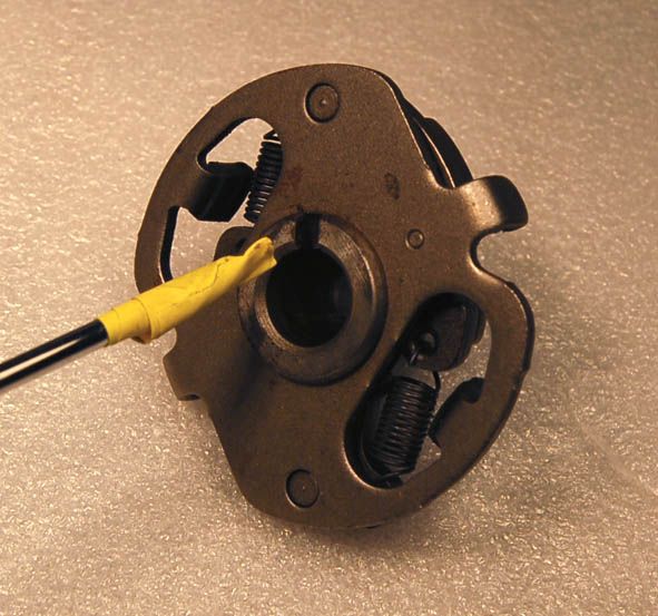
and remove the points-cam and advance assembly
(you don't really need to do this, but it'll give you a chance
to check if it's OK. Might as well do it. You probably won't
get in there the next many years)[(#) see note at the end of this post]
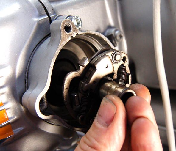
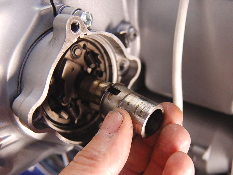
Move the bob-weights outwards
so you can wiggle/pull out and remove the cam-"sleve"/"tube".
This can be very tricky, but please do not use force!
(picture taken before removal of advance unit)
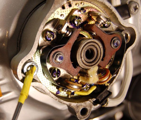
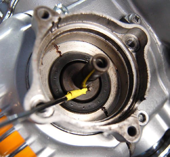
and replace it with the black plastic signal-unit/rotor that
comes with the Dyna set,
after lubricating the axle/shaft of the advance-unit
You need to get the two cut-outs on the signal-unit/rotor
to come down and let the two weight-'arms' in:
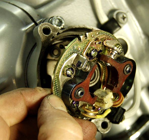
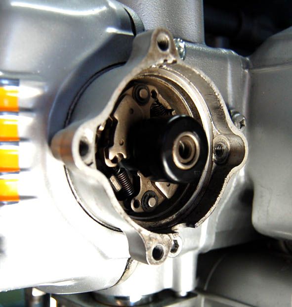
Check that everything moves absolutely freely,
that nothings is stuck, check if springs are OK;
Test by holding the edges of the assembly,
and rotate the black plastic sender unit
so the weights moves outwards
...then let it go.
The springs should freely return the sender unit to the static position.
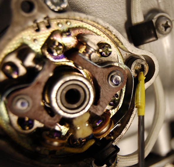
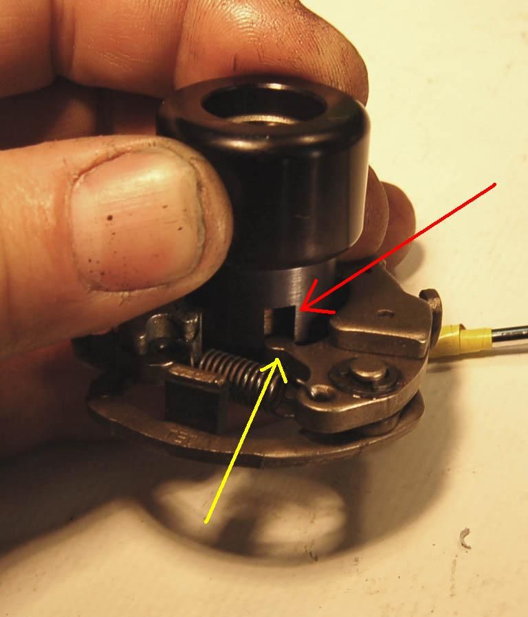
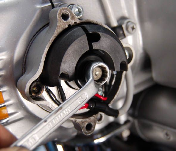
Now place back the advancer/signal-unit back on the shaft/axle.
Note that there's a slot on the back
which must fit into the little corresponding 'pin'
Now it should look like this
Install the DYNA unit
and screw in the two screws (in this case allen screws) loosely
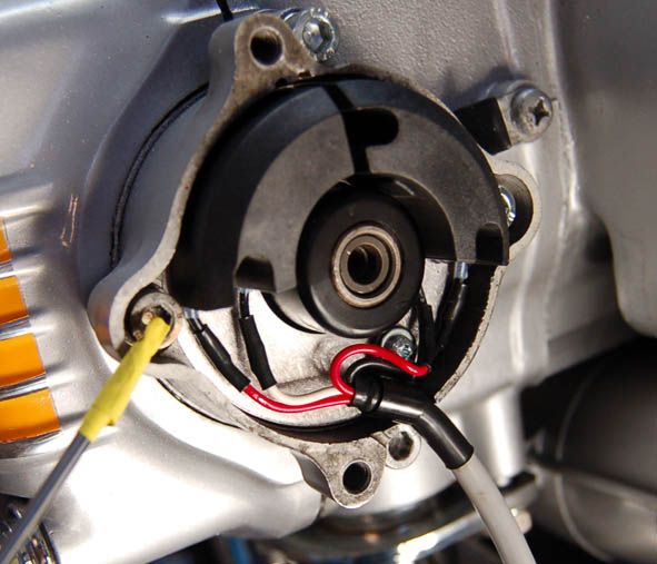
Attach 10mm bolt and washer
Connect the red DYNA supplied wire
(you ran from the WHITE/GREEN cable)
to the red wire down at the DYNA ignition assembly-wires
AND THAT'S IT!
(*) Note about the resistor:
IF you install the Dyna Hi-Performance Coils
you will NOT use any resistor:
You unplug the two wire to the resistor
(dump the resistor (and the coils))
..then connect those two wire
The Dyna Hi-Performance Coils will mount
in the same place as the standard coils
[(#) Note to the advance mechanism]
As the RPM goes up, the bob-weights moves outwards
because of the centrifugal forces.
This alters the position of the points-cam
(or in case of the Dyna; the black sender unit)
in relation to the shaft on which it is mounted, (and thereby; in relation to the position of the pistons)
See this VIDEO
(could get a nomination for the most boring video on Youtube...ha ha ha)
thereby triggering the ignition earlier and earlier
as the RPM goes up, and is fully advanced at over 2600RPM.
If stuck in that position you'll have faulty ignition timing at anything lower than approx. 2600rpm's.
You don't want that, so please check if your advance mechanism is OK,
as precribed above !
[EDIT: For timing/adjusting please click: DYNA ignition adjustment
.