
I posted this also on another goldwing forum, but there wasn't much response there. I hope the customizing forum here is a better fit.
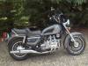
When I ran my GL with a fairing and audiosystem installed, I sometimes found that playing music would put too much load on the charging system. To monitor this, I installed a voltmeter; first a small digital one, mounted in a small metal case near the crash bars, but this didn't look right. I then decided to build a custom cockpit, with a voltmeter out of the dash on a 78 a GL1000. The project is finished, and I thought you might appreciate it, so here is a little report.
First, I made a sketch of what it should more or less look like in the end

I got myself two voltmeters to experiment with. I took them apart, and inspected them, and mixed up model-airplane enamels to match the green color of the factory gauges as close as possible. I ended up with a one-to-one mix of the brighter and darker greens, but maybe just the darker green would have been even closer. Either way, it's hard to tell the color apart from the original gauges.

Then, I took out the original cockpit, carefully took its dimensions and transferred them into the computer, adding a sleeve for the voltmeter. This was done in Inkscape which is free open source software. It was difficult to match the rounding of the gauges to the instrument panel/to get the measurements of the curves right. I ended up measuring the width of the original part at multiple points, and then calculated the radius and location of the centers of the gauges that best matched these measurements, using commercial mathematics-lab software

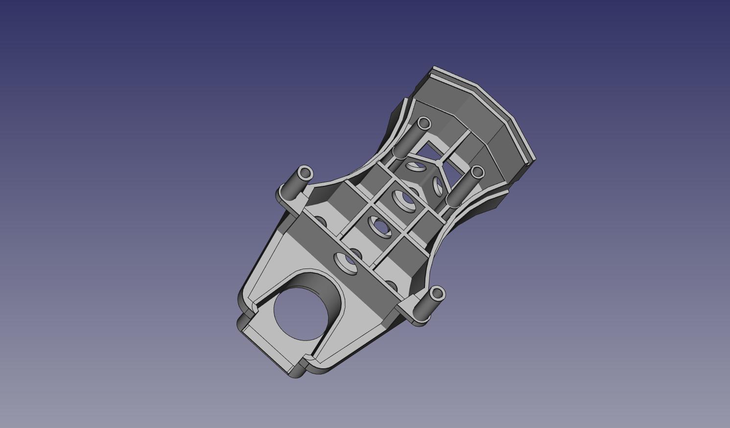
This design was only 2D, so it needed to be transferred into a 3D program. I used FreeCAD to design the part. The image below is from printing software

Once the design was finished, I got it printed. This took several tries. The first was using a simple printer my brother has at home. Unfortunately, this didn't work out very well: the part came out warped, and the pins for the screws broke off. After that, I got it printer professionally, and tested the fit of the voltmeter

This fitted well. The next step was to even out the surface, then paint it and install the voltmeter and indicator lights (LED). For this, I ordered wires and connectors that matched the honda originals as closely as I could find, so everything should connect without problems

Finally, I installed it on the bike:
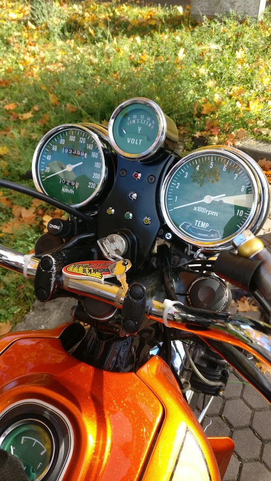
I'm really happy with the end result. Even though I no longer have the fairing/audiosystem on the bike, it is nice to be able to keep an eye on whether the bike charges properly.
Since I first fitted it, I have changed the LEDs for super bright ones: I could hardly tell whether the normal LEDs were on or off. The super bright ones are much better, although for high-beam a dim one may be a better choice. At present the high beam LED is kind of blinding!